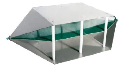
Combined with a spectrum analyzer, products can be tested before and after EMC related design modifications. A set up with a TEM cell will not deliver exactly the same quantitative results as a measurement in a certified test house, however it will give an excellent indication on whether the design suffers from excessive radiated noise or not. The engineer will clearly see, whether his changes improved or deteriorated the EMC performance or whether it remained unchanged. Using TEM cells eliminates the guesswork.
A TEM cell consists of a septum, the conductive strip in the centre section and walls which are connected to ground. The geometry is designed to present a 50Ω stripline. The device under test (DUT) is placed in between the bottom wall and the septum.
The TBTC0/1/2/3 are so called “open TEM cells”, which got no side walls for convenient placement of the DUT. It may pick up RF background noise, which however can be taken into account by doing a measurement of the cell output signal before powering on the DUT.
▪ Length: 1038 mm
▪ Width: 501 mm
▪ Height: 305 mm
▪ Septum height: 150 mm
▪ Rectangular area under the septum: 36 cm x 48 cm x 15 cm
▪ TEM cell connectors: N-female
▪ Nominal cell impedance: 50 Ohm
▪ Wave impedance: 377 Ohm
▪ Maximum RF input power: 25W (limited by supplied 50 Ohm Termination)
▪ Input return loss: S11 up to 700 MHz < -16dB
▪ Transmission loss: up to 730 MHz < 3 dB
▪ Connectors: N-Male/Female
▪ Nominal impedance: 50 Ohm
▪ Max. continuous RF power: 2W
▪ Max. continuous RF voltage: 50V RMS
▪ Frequency: 500kHz to 6 GHz
▪ VSWR: ≤ 1.2
▪ Connector: N-Male
▪ Nominal impedance: 50 Ohm
▪ Max. continuous RF power: 25W
▪ Frequency: DC to 3 GHz
▪ VSWR: ≤ 1.2
▪ Third order intermodulation: ≤ 120 dBc